The intent of this white paper is to give a reader with some familiarity with radios and wireless devices, but no experience with antennas, a better understanding of what antennas are, what they do, and why the size constraints of modern wireless devices make them especially challenging products to design antennas for. Most of the IP related to wireless device antennas involves minimizing the performance compromises relative to how antennas would perform if size and shape were unlimited. To help the reader understand the performance tradeoffs, this paper will first present some background information on antennas and radio waves. For more information on measuring, planning and assessing the performance of wireless devices, view our Network Drive Testing page under our Engineering Support Services.
A Few Basic Wireless Technologies Changes
“Wireless” devices are so common in everyday life, that almost no one thinks of the literal meaning as “not needing wires.” The devices we now carry around with us would be useless if they had to be connected like a land line phone. What makes wireless possible is the ability to carry information on radio waves, and that a sufficient percentage of the power that exits a transmitter arrives at a receiver some distance away, where the information can be extracted from the radio wave. The topic of this paper is not how information is imparted onto and extracted from the radio wave (modulation and demodulation), but how enough radio frequency energy can make its journey from a transmitter to a receiver.
Radio waves are electromagnetic energy that propagates through space. The behavior is characterized by Maxwell’s Equations. Fortunately, all you need to know about Maxwell’s Equations is that a changing electric field creates a changing magnetic field, a changing magnetic field creates a changing electric field, and this continues at the speed of light (300,000,000 meters per second) resulting in the propagation of electromagnetic waves. Electric and magnetic fields can exist in a vacuum. So unlike sound, which is a pressure wave in air, radio waves can propagate through empty space.
In a way similar to sound waves, there is negligible absorption of radio waves as they travel over distance. However, their intensity decreases with the square of distance due to angular spreading. To explain this decrease, imagine you connected a transmitter to an antenna, and you could place that antenna in the center of a sphere. You also had the ability to measure the power intensity at every point on the surface of that sphere. Now, imagine you doubled the radius of the sphere. This also means you quadrupled the surface area. The same total power passes through the surface of both spheres. But, the power per unit area (power density) is four times less.
This is also similar to the reason sound intensity decreases as the square of the distance from the source of the sound. The air does not absorb the energy. Instead, the area the sound spreads over increased by the square of the distance, and this reduces the intensity to the same degree. Another useful analogy between radio and sound is only a very small fraction of the power “transmitted” must be “received” to successfully hear it. Only a tiny fraction of the sound power from a speaker’s voice vibrates the ear drums of each of the listeners.
In a similar manner, but to a much more extreme degree, the antenna on a radio receiver only has to “pick up” a small fraction of the power the transmit antenna sent off into the world. How little? Extremely little. For example, a typical cell phone receiver sensitivity limit is -100 dBm (decibels relative to one milliwatt). A typical transmitter power for a cell tower is 10 Watts (+40 dBm). That’s a difference of 140 dB, a ratio of 1: 100,000,000,000,000.
Understanding the Technology of Antennas
Antennas are transducers. Transducers are devices that convert energy from one form to another. In the case of antennas, the two forms of energy are conducted radio frequency power (called that because it flows as current on conductors, such as circuit board traces or coaxial cable). The other form of energy is radio waves. Radio waves propagate through space. An antenna has metal terminals (such as a connector or solder contacts) that connect to the conducted side, and a structure that interacts with electromagnetic waves, to launch or receive them.
Apart from the frequency (units of cycles per second, or Hz), conducted radio frequency power is very similar to the alternating current (AC) that powers the appliances in our homes. Household power registers at a frequency of 50 or 60 Hz and radio frequency power used for wireless devices roughly falls within the 400 MHz – 6,000 MHz range. Conducted radio frequency power applied to the terminals of an antenna, as with cellular phones, is propagated away from the antenna as a radio wave because antennas are bidirectional transducers. More specifically, antennas in the presence of a radio wave will also convert some of the energy from that radio wave to conducted power at its terminals. The efficiency of this power generation by antennas can theoretically be up to 100%, meaning all of the conducted power could be radiated away from the antenna itself.
How Antennas Work
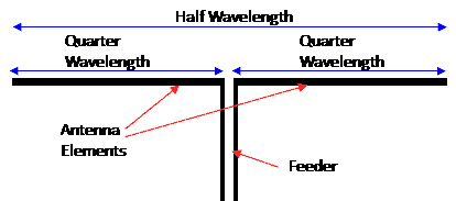
Figure 1. Half Wavelength Dipole Antenna. One of the most basic antenna types.
To describe how an antenna works, I will use one of the most basic antenna types, the half wavelength long dipole (Figure 1).
A common question asked when looking at a dipole antenna is how can something that looks like an open circuit draw any current? It is true that at DC, this antenna is an open circuit and would draw no current. However, interesting things happen when the antenna length is one half wavelength of the applied frequency. For example, a half wavelength at the 850 MHz cell phone frequency is 175mm (7 inches). Because there is a reflection from both open ends of the antenna, and the round trip between the ends is one full wavelength (or 360 degrees in phase), the reflected power adds perfectly in phase with the applied power.
This condition is called resonance and allows the current in the antenna elements to build up to a relatively high level. Much higher than it does at frequencies some percentage above or below resonance. An analogy is a swing set, which is a pendulum. Additional height can only be obtained when the person on the swing moves his body (pumps) at the resonant frequency of this pendulum. Moving at any other frequency won’t accumulate much energy (as demonstrated by children when they first attempt to use a swing set without help).
Ok, how does this relatively high current (at or near the resonant frequency) on the dipole elements radiate? Recall from physics, that there is a direct relationship between the current flowing on a conductor and the magnetic field surrounding that conductor. The changing current (because it’s AC) in the dipole elements causes a changing magnetic field around the elements, and this changing magnetic field creates a changing electric field, and from there that causes a changing magnetic field and so it continues to propagate away from the antenna as an electromagnetic wave.
Note that there is also an electric field that runs between the antenna elements. However, it only has a small contribution to the radiation of a half wave dipole. As mentioned before, all antennas work both as transmitting antennas and receiving antennas, and they have similar characteristics (resonant frequency, radiation pattern, etc.) when receiving or transmitting. This property is called reciprocity.
The Goal of Antenna Technology
We want devices to communicate without a physical connection. The basic function of a pair of antennas is to deliver enough of the power from a transmitter to a remote receiver. Before diving into the parameters that describe antenna characteristics, it might help to give one more example of the relationship between transmitters and receivers – that has nothing to do with how antennas work. I will compare a pair if distant antennas to a lossy coax cable. Think of a pair of antennas spaced far apart, that are fixed in their positions, and you only have access to the connectors on these antennas. All you can measure is the coupling between these antennas. For example, you connected a 0 dBm (1 milliwatt) signal generator to one antenna and you measured -100 dBm (0.0000000001 milliwatt) with a power meter from the other antenna.
You could think of these antennas and the distance between them as a coaxial cable with 100 dB loss. Because of reciprocity, you would also measure -100 dB if you swapped the transmitter and power meter to the opposite antennas, just like a coax cable has the same loss in both directions. If you connected this coax cable between the output of a transmitter and the input of a receiver, the receiver would see the same signal as it does with the antennas in this example. Think of a pair of antennas as a wireless lossy cable – that hopefully does not have more loss than you can tolerate. Of course, since wireless antennas move, the lossy coax cable analogy would only represent a point in time. The coupling between moving antennas typically has rapid and large variations.
Parameters of Antenna Technologies
The important antenna parameters are: frequency bandwidth, efficiency, gain & radiation pattern, effective aperture, polarization and isolation from other antennas.
Frequency Bandwidth
The frequency bandwidth of an antenna is the frequency range, or ranges, over which an antenna must perform acceptably. A common limit for the lower and upper boundaries of the frequency ranges are an impedance mismatch that causes 25% reflected power (equivalent to a 3 : 1 SWR, or a return loss of -6dB).
Efficiency
Antennas have the same efficiency value (percentage, or in decibels) when transmitting and receiving. It is easier to describe efficiency when using an antenna with a transmitter. A transmitter is connected to the terminals of an antenna through some type of transmission line. This is typically a circuit board trace or coax cable. Signals on transmission lines can travel in both directions. The signal in the direction from the transmitter toward the antenna is called the incident power. Any power reflected from the antenna back toward the transmitter is called reflected power, or return loss. The fraction of power reflected is due to the degree of antenna impedance mismatch.
For wireless devices, the common definition of antenna efficiency is the ratio of the radio wave power that radiates away from the device, to the incident power from the transmitter. It is worth noting that antenna text books often define efficiency as the ratio of radiated power to “accepted” power. This definition is similar, but neglects the effects of reflected power due to impedance mismatch, which can be significant. The “common” definition given above accurately accounts for the differences between conducted and radiated performance. Reflected power and absorbed power (which turns into heat) are the reasons real antennas always have less than 100% efficiency.
As mentioned above, reflected power is due to impedance mismatch. Absorbed power comes from the finite conductivity of metal, dielectric losses in the device, coupling to other antennas, and interaction with the head and hands of the user. Typical efficiency values are 40% (-4 dB) when away from the user (the “free space” condition), and 10% (-10dB) when head and hand effects are included.
Antenna Gain
This term can cause confusion because a metal structure cannot add power in the way an amplifier can. To describe gain, it helps to first describe what an antenna radiation pattern is. For a transmitting antenna, the power radiates away in all directions. However, the intensity of the power is not uniform. A radiation pattern is a plot of the distribution of radiated power over a spherical surface. The coordinates could be azimuth and elevation, 0 to 360 degrees and -90 to +90 degrees, respectively. Spherical coordinates can also be used. The 0dBi gain reference value is a lossless isotropic antenna. Such an antenna does not actually exist. It is a theoretical antenna that radiates 100% of the incident power uniformly in all directions. The non-uniform radiation pattern of a real antenna will be greater in some directions than other directions.
Real antennas may have gain values that exceed 0 dBi in some directions (positive gain), but the extra power in that direction came at the expense of less power in another direction. A convenient property of using dBi as a reference is the gain averaged over all directions is also equal to the antenna efficiency, because it represents the total power radiated. This will always be a negative dB value since efficiency is always less than 100%. All antennas have the same radiation pattern transmitting and receiving. It is just easier to mentally picture the flow of power in the transmitting direction.
What is the best radiation pattern for a handset? The answer is all are about equal. The reasons for that answer is the position of the handset is random and constantly changing. While the radiation pattern is fixed relative to the antenna, the radiation pattern is changing relative to the environment because the antenna is being moved relative to the environment. In addition, because handset antennas are small in terms of wavelength, their radiation patterns are very broad (no high peaks or deep nulls). And finally, reflections and scattering result in signals coming from almost all directions. There is almost never a direct, line of sight, condition between the cell site and the handset.
Effective Aperture
The effective aperture of an antenna is a measure of how effective an antenna is at receiving the power of radio waves. It can be described as the receiving cross section of the antenna. It is directly related to gain (described above) and wavelength squared. Effective aperture is presented here because it helps to understand the relationship between the power an antenna receives relative to the intensity of a passing radio wave. Note that the intensity of that radio wave is related to the transmitter power, the gain of the transmitter antenna in the direction of the receiver, and inversely proportional to the distance squared between the antennas.
Polarization
Electromagnetic waves have both electric fields and magnetic fields. The electric and magnetic fields are perpendicular to each other, and both are perpendicular to the direction of propagation. By convention, the direction of the electric field defines the polarization. For example, a vertical dipole antenna will radiate a vertically polarized radio wave. A horizontal dipole will radiate a horizontally polarized radio wave. A dipole tilted at 45 degrees will have half its power vertically polarized, and half its power horizontally polarized. A vertical dipole will only receive the vertically polarized component of a passing radio wave. For example, a vertical dipole will receive no power from a horizontally polarized wave.
The lost potential power is called polarization mismatch. What antenna polarization is best for most wireless applications? The answer is all polarizations work about equally well. Wireless devices are randomly moved and that randomizes the polarization of their antennas relative to the environment. Furthermore, reflections and scattering of radio waves from the surrounding environment further randomizes them. Therefore, over even very short time periods, the polarization mismatch statistics would be roughly equal for any polarization.
Isolation
Antenna to antenna isolation is the coupling, measured at the terminals, between two antennas on the same wireless device. It is measured at the frequencies that both antennas operate. It is the same in both directions. Poor isolation negatively impacts performance because it is a source of loss for the other antenna. It can also cause one transmitter to overload the receiver on the other antenna. Isolation is impacted by the antenna designs, where they are located on the unit, and the frequency range of both antennas.
Antennas for Wireless Devices
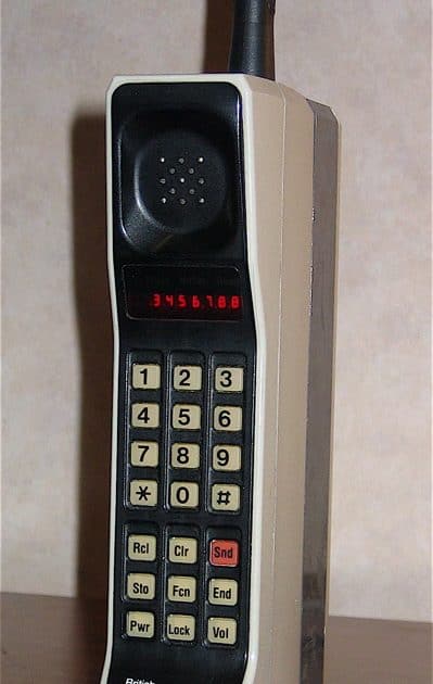
Now that you have a better understanding of antennas, let’s dive into some of the challenges when it comes to wireless devices. One of the first cell phones (aka, brick phone) is shown in figure 2.
The antenna designers for this phone had it easy. It only had one antenna and that antenna covered a single frequency band, the 824 MHz to 894 MHz original cellular band. The antenna was also large and external to the handset. Compare this to the half wavelength dipole. Note that a dipole does not need to have both elements the same thickness or length. In the case of this phone, the phone itself is one element of the antenna and the structure called the “antenna,” is the other element.
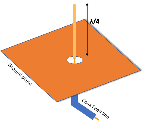
A way to save space over the half wavelength dipole is to use a single element and “feed it against” a relatively large ground structure. This is called a monopole, which is shown in Figure 3.
Counterpoise
The ground structure is called a counterpoise. For most handsets today, the circuit board and metal structures in the handset that attach to it form the counterpoise for all of the antennas. A problem with this antenna is it extends away from the handset. This was still acceptable in the days of external whip or stubby antennas. While these were in use, the one way to save space was to make them shorter than a quarter wavelength. This resulted in a poor impedance at the operating frequency. The impedance was transformed back to the desirable impedance (typically 50 Ohms) using a matching network of inductors and capacitors.
However, the problem of using a matching network is the components have loss, and an electrically short antenna tuned with a matching network has a narrower bandwidth than a full-sized antenna. The matching network loss reduces the antenna efficiency in the center of the band, and the narrower bandwidth increases impedance mismatch losses at the edges of the frequency band.
Figure 2. the “brick phone.” Almost no compromise needed for the antenna design.
Photo by: Redrum0486. Retrieved 9/26/17 at https://commons.wikimedia.org.
Figure 3. The monopole antenna.
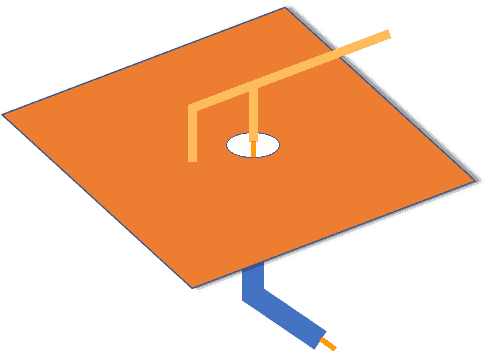
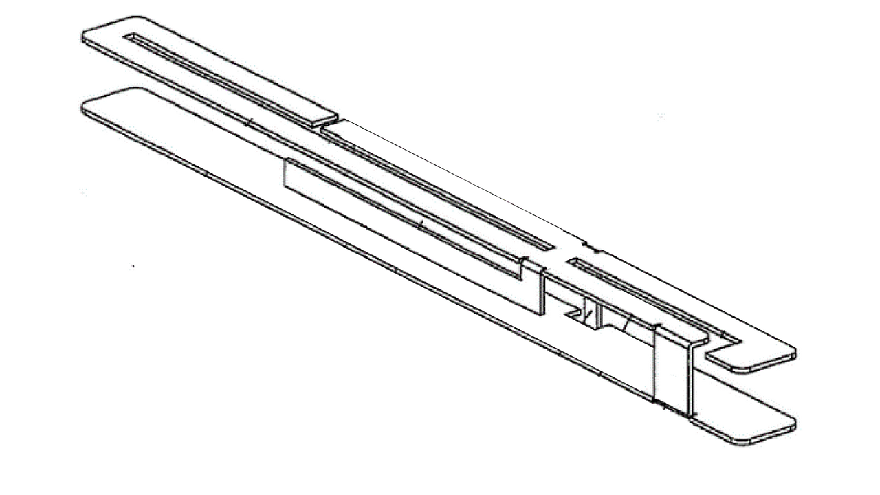
Figure 4. The wire inverted F (WIFA) antenna.
As the look of external antennas became unpopular, there was an incentive to use internal antennas. That resulted in the antenna design called the wire inverted F antenna, or WIFA. One is shown in figure 4.
Think of a WIFA as a monopole that was bent over part way up its height, so that most if its length lies over the ground. This gets it to lie close to the circuit board so it can remain internal to the handset. However, like anything that saves space, there is a price to pay in terms of performance. Moving much of the length of the antenna element much closer to the ground metal adds a lot of capacitance between the element and the ground. This detunes the impedance of the antenna. Adding parallel inductance between the antenna feed and ground will tune that capacitance out at the center of the band. This is accomplished through the shorted portion of the antenna (left side in Figure 4). It forms a physically large one-turn inductor to ground, which has less loss than alternatively using an inductor component on the circuit board.
The addition of the tuning inductance still adds some loss, and only cancels the effect of the capacitance at the center of the frequency band. Relative to a monopole, a WIFA has a lower efficiency and a narrower bandwidth. But, the benefit is no external antenna. Sometimes a similar antenna is called the planar inverted F antenna (PIFA). The only difference is the width of the conductor. However, both are very similar. The terms PIFA and WIFA are often used interchangeably. Note that the height of the element above the ground is a variable in the design. Increasing the height reduces the undesirable capacitance between the element and the ground and moves the performance towards that of a monopole. Another technique used to reduce the capacitance is to clear away as much of the metal under the antenna as possible. So, the design of WIFA antennas is a tradeoff between fitting them closer to ground metal and performance.
Multi-Band & Shared Use Antennas
Today there are many frequency bands used for voice, data, GPS, Bluetooth, WiFi, and other functions. Often a multi band antenna will serve two radios with a filter (called a diplexer) to send the two frequency bands to each of the radios. An example is GPS is sometimes shared with Bluetooth. To accommodate multiple frequencies, several different antenna element lengths are connected to a common feed point. Figure 5 is an example of a multi-frequency WIFA.
Figure 5. Multi-element WIFA.
At different frequencies, different elements of this antenna are resonant. At a frequency that one element is resonant, the non-resonant elements present a very high impedance, and therefore conduct almost no current. Resonances can also be produced in the way that the elements fold back on themselves, run next to other elements, or have gaps between them. This results in some portions of the antenna structure having resonances at multiple frequencies. One of the biggest challenges today is designing these WIFA (or PIFA) antennas to cover all the needed bands in the limited volume provided for the antennas.
The design of these antennas is a combination of science and experience. Computer modeling allows for rapid evaluation of design iterations, but does not provide guidance to the engineer as to which dimensions to change. Another challenge is antennas require some open space around them to not “short out” the electric fields. All other components within a handset can be packed in against each other. Inexperienced project managers sometimes assume the antennas are just another component, and have trouble providing “empty volume” within handsets for invisible fields.
Multiple Antennas
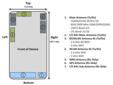
Figure 6. Multiple antennas. The Samsung Galaxy S5 has seven.
All modern handsets have multiple antennas. Figure 6 shows the Samsung Galaxy S5 as an example of a handset with seven antennas. Some of the challenges antenna engineers must contend with are: limited volume, adequate performance over the full frequency range of every band, poor isolation between antennas, high losses from very close proximity to the head and hand.
I will give a short description of each of these challenges. Volume. Items such as the battery, display, sensors, etc. all compete for the volume within a handset. Antenna engineers sometimes generate graphs of size vs. performance for the project manager to prioritize the areas allocated to antennas. The best antenna engineers, and the best IP, extract the highest antenna performance for a given volume. Adequate performance frequency bandwidth. Also, strongly related to volume. It often comes down to acceptable performance roll off at band edges in exchange for smaller size.
Poor Isolation
Given that all antennas share the same ground metal of the handset for their counterpoise, it means that they also share a significant part of their radiating structure. This can make adequate isolation difficult. It helps when the two antennas don’t share any frequencies. The relative location of the antennas has some impact on isolation. Further apart is not always better. Head and hand losses. These are especially high in thinner phones, often 10 dB, due to the very close spacing between the antennas and head and hand. One choice that can help is place the data antenna at the top of the handset because typically for data use the top of the handset is not against the head. This leaves the bottom of the phone available for the voice antennas. While users typically hold the top of the handset against their heads, there is usually several cm of separation between the bottom of the handset and the face and hand.
Impact to System Performance from Compromised Antennas
Reductions in antenna performance (efficiency) will result in lower receiver sensitivity and less radiated power. This causes a reduction in range, due to the power vs distance relationship. For example, cell site density has to be increased, WiFi distance is less. For GPS, range reduction is not an option. The result of reduced antenna performance is greater instances of not getting a position fix, particularly in already difficult locations such as indoors, or in dense city locations (called urban canyons).
What Would a Handset Antenna Engineer Ask for If There Were No Constraints?
The answer is larger and thicker handsets. Greater length and width would allow for larger antennas. This is especially for the lower frequency bands, where the longer wavelengths require longer antenna elements. The larger dimensions would also allow the antenna structure to extend out beyond the ground metal, greatly reducing the antenna to ground capacitance. A larger handset also provides a larger counterpoise. This improves antenna to antenna isolation, and increases the bandwidth of the lower frequency antennas. Thicker handsets would also help increase the antenna to ground spacing. They would also increase the antenna to body separation, which would reduce body loss.
We are constantly updating our white paper section with new technical write ups featuring our expertise across our growing catalog of technology and industry specializations. Contact us for more information about Antenna design and wireless technologies.

